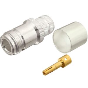
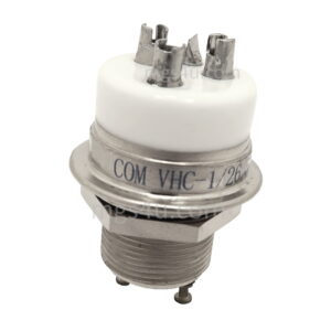
UHF Female Crimp Connector for LMR-600, RG-217/U, and other 0.590 Inch OD Coax
Silver Plated Brass Body
Silver Plated Brass Center Pin
PTFE Dielectric
“TSS”
Detailed Product Information
Description
This UHF Female Crimp Connector is one of several thousand RF products available from Max-Gain Systems, Inc.
This connector is made from a Solid Brass body that is precision machined and plated with Silver for superior performance and value. This UHF Female Crimp Connector has a PTFE dielectric and a silver plated brass center pin. The UHF Female interface (also known as a SO-239 connection) is by far the most popular connection type used in Amateur Radio.
7506-UHF-600, 7506-600
Compatible with Coaxial Cable Types: LMR-600 and RG-217/U coaxial cable.
Installation Guide:
We will begin by installing the UHF female connector on a piece of LMR-600. This process is the same for all the other types of cable with an outer jacket OD of 0.590. These connectors fit on a wide range of coax types including, but not limited to: RG-217/U, LMR-600, and other 0.59 inch OD coax.
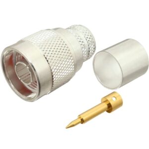
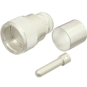
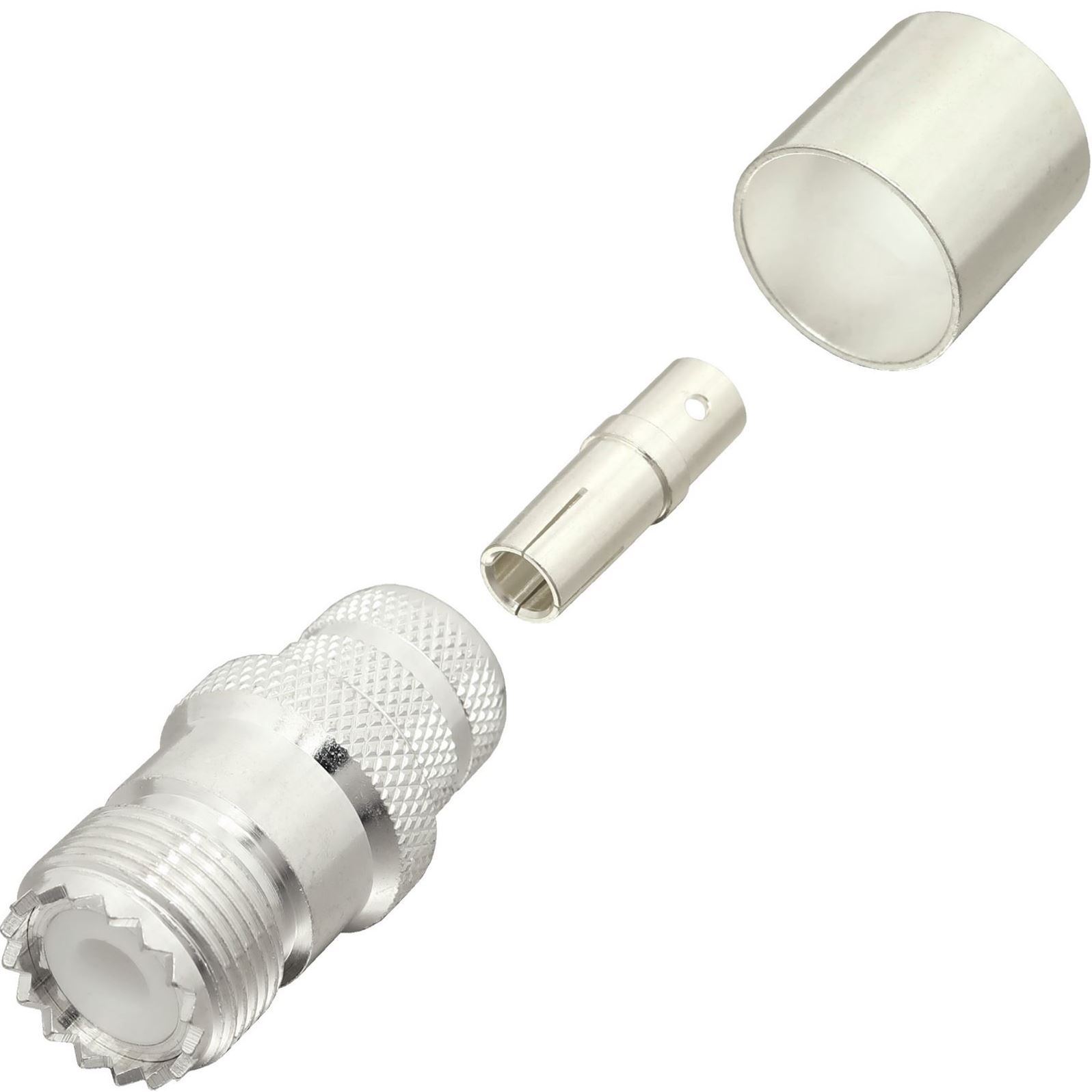
Identify all connector parts (3 parts):
Each connector consists of one body assembly (jack), one rear ferrule (crimp sleeve), and one center pin (jack contact).
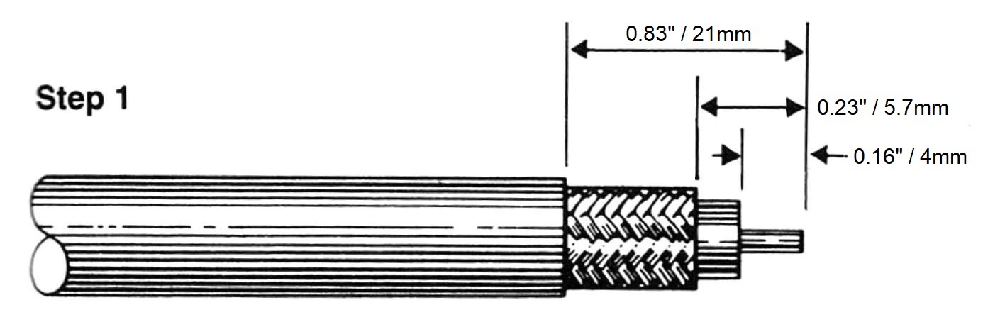
Coax Stripping:
First cut your cable to the desired length and then strip the black jacket back approximately 0.55 inches. When the jacket is stripped cut the braid/foil back 0.225 inches from the fresh cut end. Finally, cut back the dielectric 0.16 inches from the fresh end down to the center conductor. The braid needs to be cut back further than the dielectric to insure that none of the braid or foil is touching the center conductor which could cause a short.
Note: Do not nick the braid, dielectric, and center conductor if at all possible. Tinning of the center conductor is not necessary if contact is to be crimped. For solder method, tin the center conductor if the center is stranded. twist the center conductor very tightly prior to tinning.
Installation Method Selection:
Slide the outer ferrule onto the coax as shown below. Flare the braid slightly to allow insertion of the connector main body. Important: Do not comb out braid.
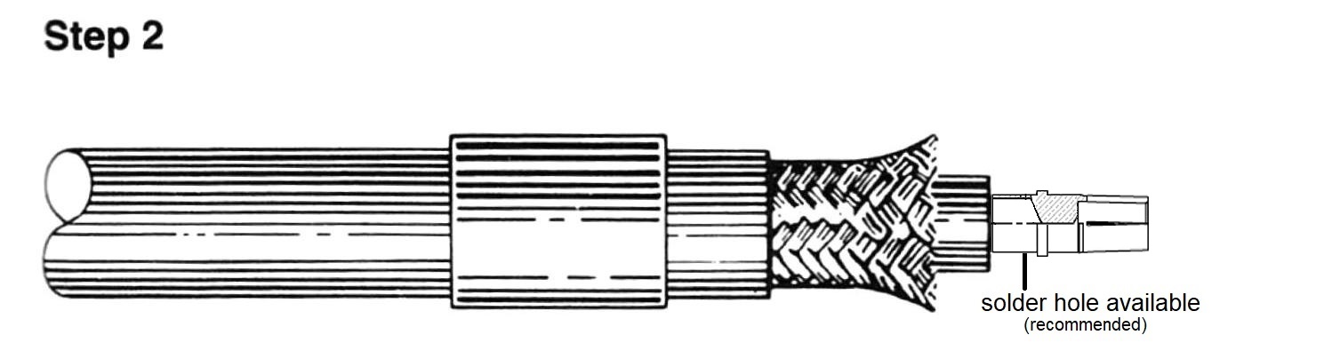
Place the center contact on the center conductor of the coax so that it butts against the cable dielectric. The center conductor should be visible through the solder / inspection hole of the contact. Solder contact in place as follows:
Crimp-on the Ferrule
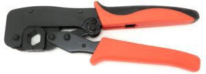
Use the 7505-HANDLE-600 crimp handle for the ferrule. (DO NOT CRIMP / CRUSH THE CENTER PIN)
Solder the Pin
Make sure the solder hole is facing up. Touch the soldering iron to the underside of the center pin directly under the solder hole. Touch the solder to the center conductor through the solder hole on the center pin. Allow the heat from the metal to melt the solder so that it wicks into the center pin. Once the solder melts it only takes a tiny amount of solder to make the connection. Do not allow the solder to pool over the solder hole. The outside of the center pin should be free of obstructions for insertion. Do not over heat the center pin which could cause swelling of the dielectric of the coax.
Main Body Install:
Install the cable assembly with the center pin already affixed, into the main body of the connector. The knurled portion of the main body slides under the braid of the coax. Push the cable assembly into the main body until the center pin snaps into place in the dielectric of the connector.
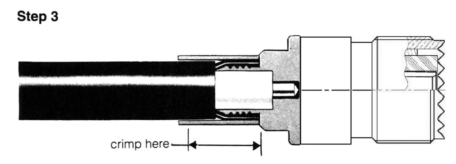
Slide the ferrule (placed on the coax at the beginning of Step 2) over the braid and completely up against the connector body. Using the 0.590 hex of the 7505-HANDLE-600 crimp handle, crimp the ferrule at the location shown in the picture below (on the ferrule, but right up against the main body of the connector).
Final Testing:
When this is completed, as a final test, you should always check resistance from the center pin to the body with an ohmmeter in a low resistance scale. After verifying that there are no braid – to – center pin shorts on the other end of the coaxial cable, you should see infinite resistance (open).
See our entire line RF Connectors and Adapters:
RF Connectors
RF Adapters
About Max-Gain Systems, Inc.
Max-Gain Systems, Inc. carries a full line of in-series, between series, right angle, T-shaped, quick connect, handie-talkie (BLACK), pigtails (coaxial jumpers), etc… RF adapters. Our RF adapter lines are constantly expanding. We keep our RF connector and adapter lines in stock. We ship both retail and wholesale quantities. To become a dealer / wholesale user, contact us with your potential usage.
Max-Gain Systems, Inc. is the number one supplier of fiberglass round hollow tube, square tube and round solid rod to the antenna manufacturing industry. We produce millions of feet a year for hundreds of different industries including but not limited to: marine / boating, aeronautical, agriculture, construction, emergency services, etc…. We have the unique ability to sell one piece or even a semi-truck full. Feel free to prototype using our fiberglass tube and rod then contact us for a quote on a production run. At production run quantities we can cut to your desired lengths at no additional charge, and we can also perform several different fabrications (example: drilling holes in precise locations along a tube) to ensure your delivered material is ready for assembly. We have several accessory items designed for our fiberglass including but not limited to: couplers, telescoping clamps, ferrules, etc…