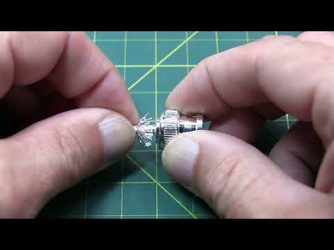
Alan Wolke (call sign W2AEW) of the YouTube channel w2aew (https://www.youtube.com/w2aew), purchased some of our BNC male connectors to go on to RG-174 coax for his own personal use. He used them and loved them and produced a fantastic video that is a must see. Very in depth and thorough. Check it out here:
Installation Guide for the connector used:
This install guide depicts a BNC male connector onto RG-174 coaxial cable. The techniques used in this installation guide can be used for almost any crimp on type connector.
We will start with the “FAQ” in order to save you some time at the beginning.
Connector Install FAQ
1.) The center pin is not going onto the center conductor of my coax.
It could be one of two things. If you have a solid center conductor on your coax, be sure that the center conductor is round. When you cut the coax to length, a diagonal cutter cuts by applying tremendous force to a small surface area which can “flatten” the center conductor. Use your pliers to squish the center conductor back into a round shape and it should work. If you are using a coax with a stranded center conductor, when cutting the coax, this may have “squished” the strands of the center conductor which may have loosened the wrap of the center strands. You may need to squeeze the strands back together, with your pliers, while twisting the strands back to as tight of a wrap as possible to make the center conductor smaller in diameter. If this does not work, you can use your small diagonal cutters to cut off 3-4 strands of the exposed center conductor which will immediately decrease the diameter of the wrap.
2.) I melted the dielectric of my coax.
You definitely want to avoid this where possible. By applying the soldering iron under the point to be soldered, the heat will rise quickly heating the work area. You will want to have the solder on the work at the point at which to be soldered. Once the solder starts flowing, let just enough in to give a coating onto the center conductor and so that the solder pools and fulls the “hole” in the side of the center conductor. This will provide the best connection, stop the center pin from coming off, and making the center conductor only needing direct heat for a very short duration.
Installing the BNC Male Crimp-On Connector
We will begin by installing the BNC male crimp-on connector on a piece of coax. This process is the same for all the types of coaxial cable that fit this BNC male crimp-on connector. These connectors fit on a wide range of coax types, including: RG-174, RG-188, RG-188A/U, RG-316, RG-316/U Double Shield, LMR-100A, Belden 7805R, Belden 8216, Belden 83269, Belden 83284, Belden 84316, and other 0.100 Inch OD Coax.
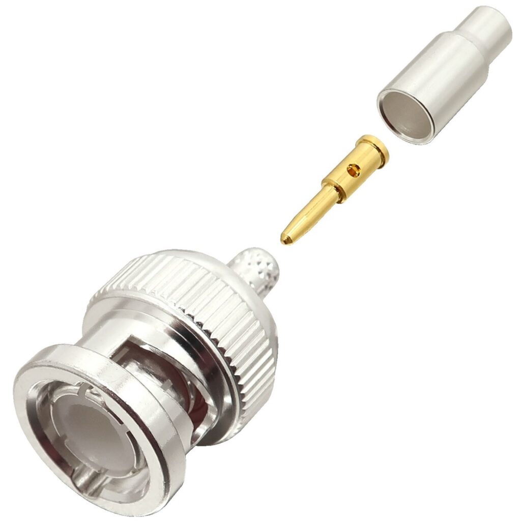
Identify all connector parts (3 Parts):
Each connector consists of one body assembly (plug), one rear ferrule (crimp sleeve), and one center pin (plug contact).
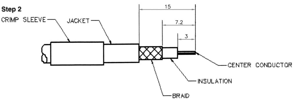
Coax Stripping:
First cut your coaxial cable to the desired length and then strip the black jacket back approximately 15mm (0.59”). When the jacket is stripped cut the braid/foil back 7.2mm (0.28”) from the fresh cut end. Finally, cut back the dielectric 3mm (0.12”) from the fresh end down to the center conductor. The braid needs to be cut back further than the dielectric to insure that none of the braid or foil is touching the center conductor which could cause a short.
Once the cable is prepped, make sure to put the ferrule (crimp sleeve) of the connector on the coaxial cable before you proceed.
Note: Do not nick the braid, dielectric, and center conductor if at all possible. Tinning of the center conductor is not necessary if contact is to be crimped. For solder method, tin the center conductor if the center is stranded. twist the center conductor very tightly prior to tinning.
Install Method Selection:
Slide the outer ferrule onto the coax as shown below. Flare the braid slightly to allow insertion of the connector main body. Important: Do not comb out braid.
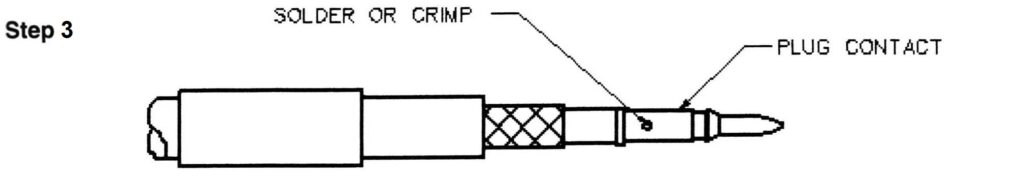
Place the center contact on the center conductor of the coax so that it butts against the cable dielectric. The center conductor should be visible through the solder / inspection hole of the contact. Crimp or solder contact in place as follows:
Crimp-on Method
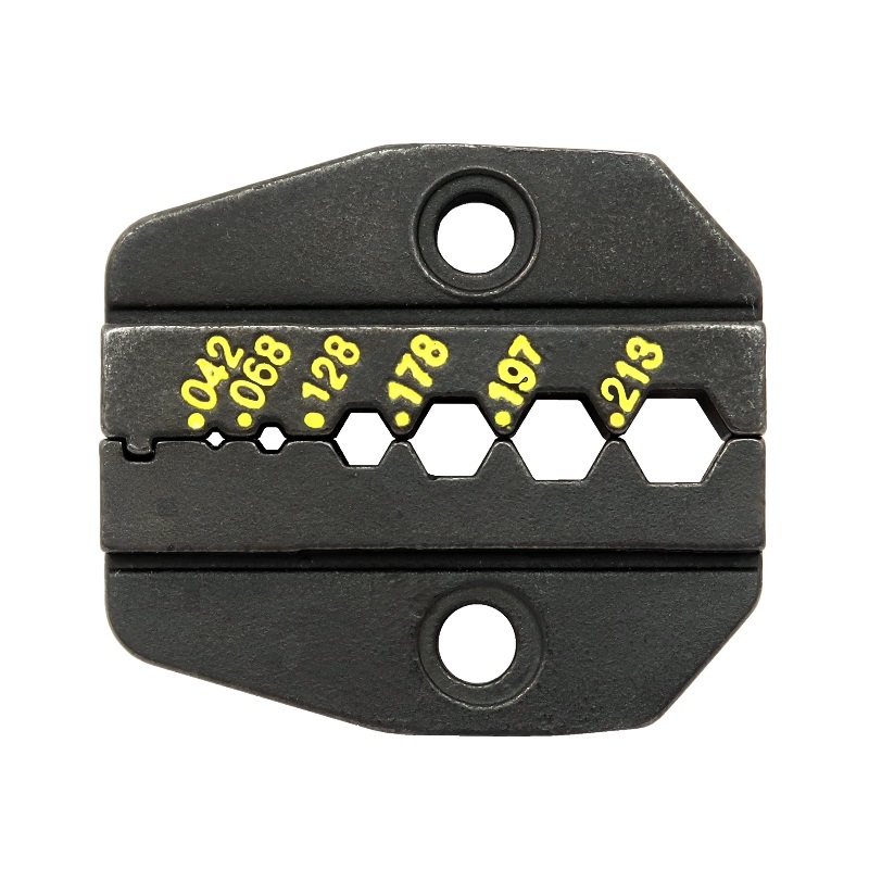
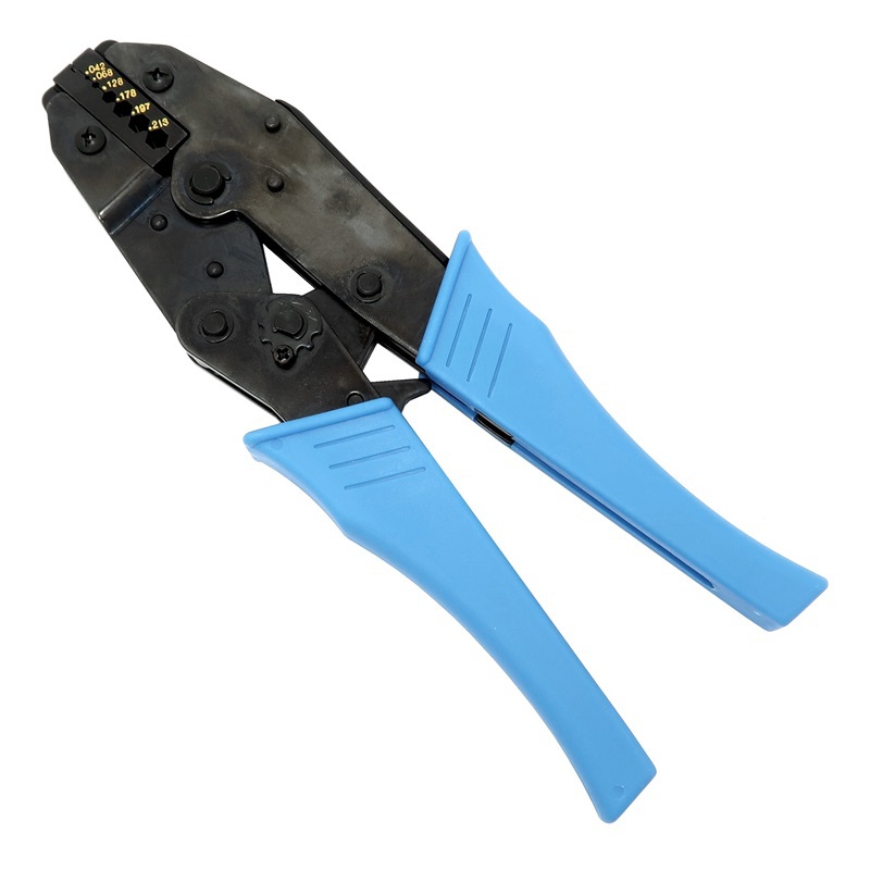
Use the 0.068” hex die from your 7505-DIE-174 ratcheting crimper die to crimp the center pin above the small lip of the center pin right on top of the “solder hole”.
Solder-On Method (preferred)
Make sure the solder hole is facing up. Touch the soldering iron to the underside of the center pin directly under the solder hole. Touch the solder to the center conductor through the solder hole on the center pin. Allow the heat from the metal to melt the solder so that it wicks into the center pin. Once the solder melts it only takes a tiny amount of solder to make the connection. Do not allow the solder to pool over the solder hole. The outside of the center pin should be free of obstructions for insertion. Do not over heat the center pin which could cause swelling of the dielectric of the coax.
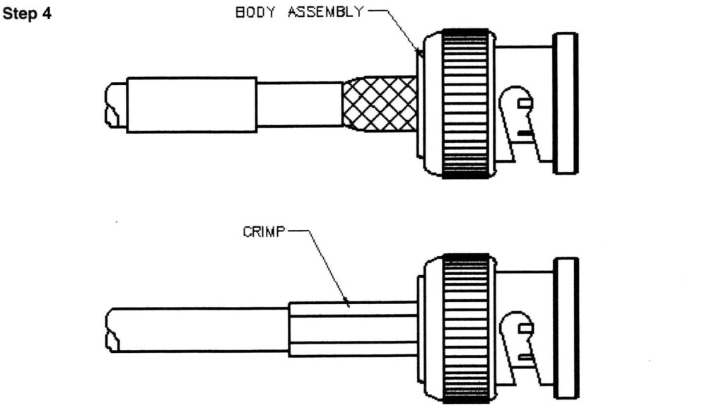
Main Body Install:
Flare out the braid of the coax and slide the body assembly over the center pin and under the braid. Then seat the body assembly firmly onto the center contact. Arrange braid uniformly around the knurled portion of the body assembly. Slide the ferrule (crimp sleeve) forward and make sure it is in contact with the body assembly. Using the 0.178” hex die from the 7505-DIE-174 ratcheting crimper die to crimp the ferrule (crimp sleeve) right up next to the main body assembly. This crushes the metal sleeve around the braid and knurling to make it difficult for the connector to be removed. Trim any braid that extends out from crimp sleeve, against the body assembly, so not have any strays sticking out.
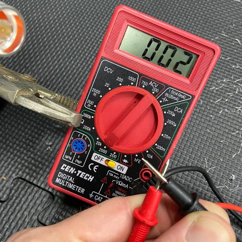
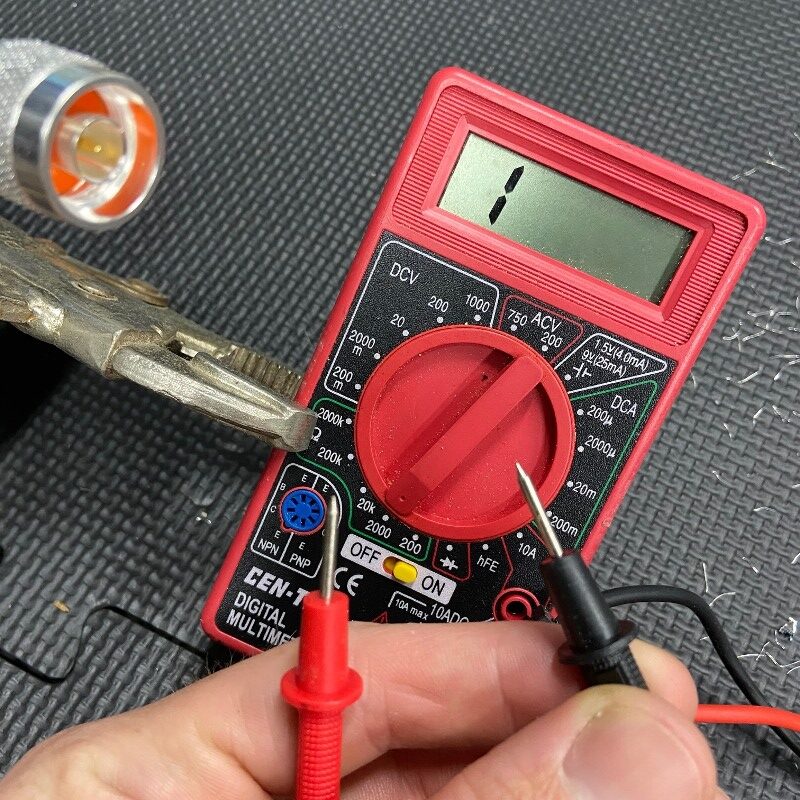
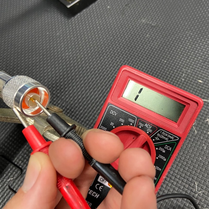
Final Testing:
When this is completed, as a final test, you should always check resistance from the center pin to the body with an ohmmeter in a low resistance scale. After verifying that there are no braid – to – center pin shorts on the other end of the coaxial cable, you should see infinite resistance (open). This completes your Type N male crimp-on connector installation, and the connector is ready for use!
Download a PDF copy for your use
You can download a PDF copy for your later use here: