Hello Fellow Radio Enthusiasts!
We want to make everyone aware of a new book by noted author Hal Kennedy, N4GG! Hal is extremely knowledgeable on a wide range of amateur radio related topics, such as antennas, construction how-to’s, tips, techniques, sourcing, reviews, and much more that you should find informative, educational, and interesting!
Hal’s books and articles (he has written for QST magazine) are ALWAYS good, and we think his latest is his new “best”! AND he even has a chapter which talks extensively about us … Max-Gain Systems, Inc! Both his first book in this series and his newest one, Ham Radio Tips & Tales, Volume II, are available from Amazon. We highly recommend them! It makes a great Christmas gift for yourself or your favorite ham! Links to both books are below.
First Book
Volume II
A skill every “HAM” needs is installing a PL-259 connector
We are going to start with the FAQ which will save time if you are new to all of this =)
1.) The center pin is not going onto the center conductor of my coax.
It could be one of two things. If you have a solid center conductor on your coax, be sure that the center conductor is round. When you cut the coax to length, a diagonal cutter cuts by applying tremendous force to a small surface area which can “flatten” the center conductor. Use your pliers to squish the center conductor back into a round shape and it should work. If you are using a coax with a stranded center conductor, when cutting the coax, this may have “squished” the strands of the center conductor which may have loosened the wrap of the center strands. You may need to squeeze the strands back together, with your pliers, while twisting the strands back to as tight of a wrap as possible to make the center conductor smaller in diameter. If this does not work, you can use your small diagonal cutters to cut off 3-4 strands of the exposed center conductor which will immediately decrease the diameter of the wrap.
2.) I melted the dielectric of my coax.
You definitely want to avoid this where possible. By applying the soldering iron under the point to be soldered, the heat will rise quickly heating the work area. You will want to have the solder on the work at the point at which to be soldered. Once the solder starts flowing, let just enough in to give a coating onto the center conductor and so that the solder pools and fulls the “hole” in the side of the center conductor. This will provide the best connection, stop the center pin from coming off, and making the center conductor only needing direct heat for a very short duration.
Installing the PL-259, UHF male Solder-On Connector
We will begin by installing the PL-259 connector on a piece of LMR-400. This process is the same for all the other types of cable that fit the PL-259 connector. These connectors fit on a wide range of coax types including, but not limited to: RG-8, RG-11, RG-83, RG-213, RG-393, LMR-400, Belden 8237, Belden 8267, Belden 9011, and Belden 9913. For smaller coax sizes a reducer will need to be used. See the 7508-S for RG-8X, RG-59, RG-6, RG-62, RG-223, LMR-240, Belden 7916A, Belden 8241, and Belden 9258. See 7507-S for RG-58, RG-58A/U, RG-142, RG-400, LMR-195, LMR-200, Belden 9201, Belden 8219, Belden 8259, and Belden 7807. See 7506-S for RG-174, RG-178, RG-188, RG-196, LMR-100A, LMR-100, LMR-110, and Belden 8216.
Identify all connector parts (2 Parts):
Each connector consists of one main body and one outer shell.

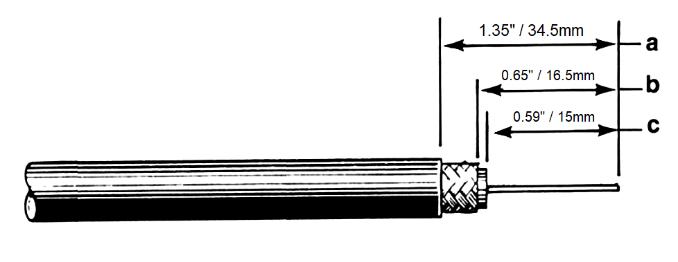
Coax Stripping:
First cut your cable to the desired length and then strip the black jacket back approximately 1 inch. When the jacket is stripped cut the braid/foil back 0.75 of an inch from the fresh cut end. Finally, cut back the dielectric 0.6875 of an inch from the fresh end down to the center conductor. The braid needs to be cut back further than the dielectric to insure that none of the braid or foil is touching the center conductor which could cause a short.
Once the cable is prepped, make sure to put the sleeve of the PL-259 on the cable before you put the body of the PL-259 on the cable, with the knurled end of the sleeve closest to the tip of the connector.
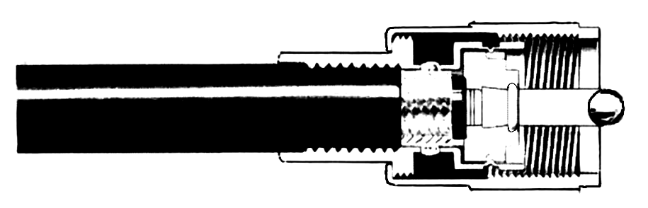
Main Body Install:
Put the PL-259 main body on the end of the cable and grip it with a pair of pliers and begin screwing it to the right (clockwise) till the center conductor is flush with the tip end of the center pin of the PL-259 connector itself.
FAQ #1: Why wont the center conductor go into the connector?
Answer 1: The center is bent off of center. Ensure the center conductor is perfectly straight before screwing the connector body onto the coax.
Answer 2: The tip of the center conductor was flattened by diagonal cutters when cutting the coax. To fix this, use a pair of pliers to round back out the tip of the center conductor.
Answer 3: The strands spread apart making the center conductor too large. LMR-400 coax is available in solid core and stranded versions. When cut, the strands of the stranded version can “loosen” and come separated. You will need to re-tighten the strands by twisting them back to their original diameter.
Soldering Guide:
This soldering guide is for soldering Max-Gain Systems, Inc. PL-259 connectors. These are approximate measurements for our PL-259 connectors, which adhere to industry standards for this type connector. If you choose to use this guide for connectors sold by others who do NOT adhere to these standards, the measurements could be off and result in a poor installation.
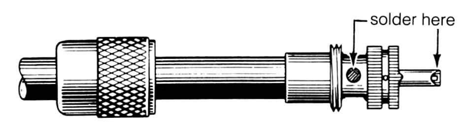
Now we begin soldering the PL-259 connector to the cable. Begin by applying heat to the center pin of the PL-259 connector with your soldering iron. Before proceeding, allow sufficient time for the soldering iron tip to reach full operating temperature and clean the tip of the iron by wiping it with a damp sponge. Be sure the soldering iron is on the bottom side of the center pin. The heat rises and heats up the pin faster. When the pin is heated, apply the solder to the tip of the center conductor. Allow sufficient solder to flow to seal the center conductor inside the center pin.
Once the center pin is sealed with solder, move the soldering iron to the holes of the PL-259. Make sure to fill all four of the holes with solder flush with the top of each hole. Once all four holes of the PL-259 are filled with solder let the connector cool down. When the connector is cool take the sleeve (which should have been put on the cable before the PL-259 was screwed on the cable) and slide it up the cable onto the connector and screw it up into place.r).
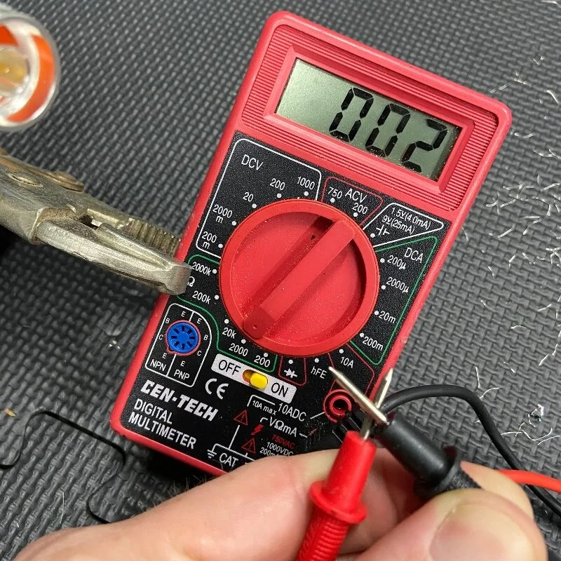
Final Testing:
When this is completed, as a final test, you should always check resistance from the center pin to the body with an ohmmeter in a low resistance scale. After verifying that there are no braid – to – center pin shorts on the other end of the coaxial cable, you should see infinite resistance (open).
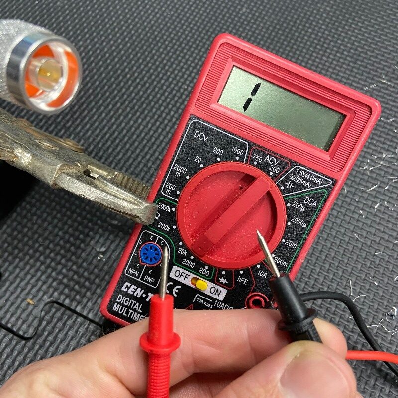
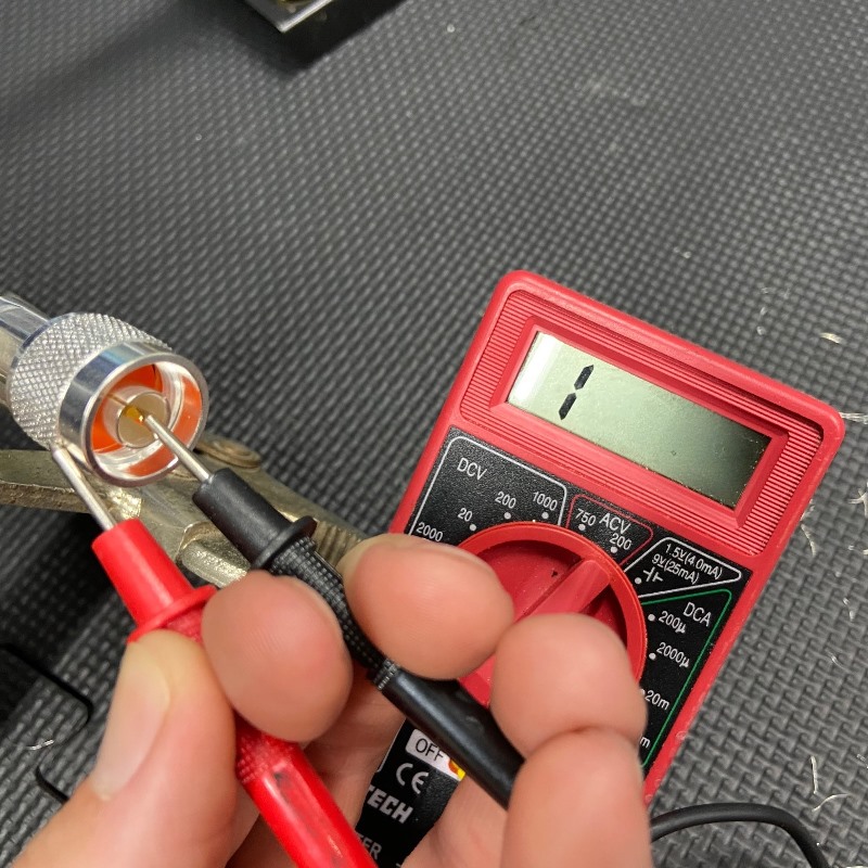
As a final check, inspect the tip of the center pin to be certain that there is no excess solder present. This could interfere with easy insertion of the tip of the PL-259 into the female (SO-239) connector. If there is a tiny bit of excess solder present, it can usually be easily removed. Lightly scrape the soft solder with the edge of a knife blade until smooth. This completes your PL-259 installation, and the connector is ready for use!
Download a PDF copy for your use
You can download a PDF copy for your later use here: