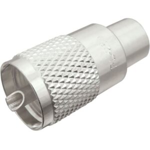
SMA Female Crimp Connector for RG-174, RG-316, LMR-100A, and other 0.100 Inch OD Coax
Gold Plated Brass Body
Gold Plated Brass Center Pin
PTFE Dielectric
“TGG”
Detailed Product Information
Description
This SMA Female Crimp Connector is one of several thousand RF products available from Max-Gain Systems, Inc.
This connector is made from a Solid Brass body that is precision machined and plated with Gold for superior performance and value. This SMA Female Crimp Connector has a PTFE dielectric and a gold plated brass center pin. The SMA Female interface’s jack and exterior threads provide a sub-miniature and tight-locking connection for use at higher frequencies.
7806-SMA-174
Compatible with Coaxial Cable Types: RG-174, RG-188, RG-188A/U, RG-316, RG-316/U Double Shield, LMR-100A, Belden 7805R, Belden 8216, Belden 83269, Belden 83284, Belden 84316, and other 0.100 Inch OD Coaxial cable.
See our entire line RF Connectors and Adapters:
Installation Guide:
We will begin by installing the SMA crimp-on connector on a piece of coax. This process is the same for all the types of coaxial cable that fit this SMA crimp-on connector. These connectors fit on a wide range of coax types, including: RG-174, RG-188, RG-188A/U, RG-316, RG-316/U Double Shield, LMR-100A, Belden 7805R, Belden 8216, Belden 83269, Belden 83284, Belden 84316, and other 0.100 Inch OD Coaxial cable.
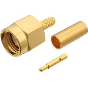
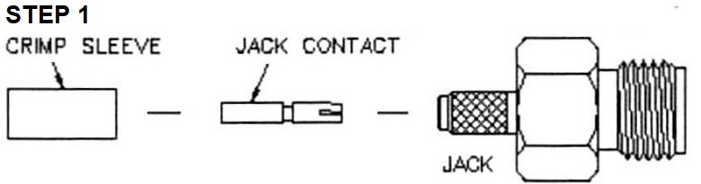
Identify all connector parts (3 parts):
Each connector consists of one body assembly (jack), one rear ferrule (crimp sleeve), and one center pin (jack contact).
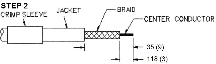
Coax Stripping:
First cut your coaxial cable to the desired length and then strip the black jacket back approximately 9mm (0.35”). When the jacket is stripped back the dielectric 3mm (0.118”) from the fresh end down to the center conductor. The braid needs to be looked at to ensure it is cut back further than the dielectric to insure that none of the braid or foil is touching the center conductor which could cause a short.
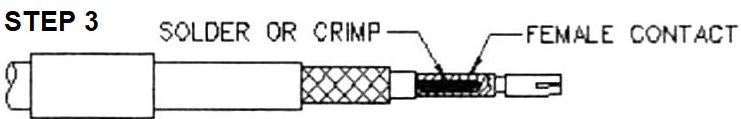
Crimping and Soldering Install:
Place the center pin onto the conductor of the coaxial cable.
Soldering Guide (preferred):
This soldering guide is for soldering Max-Gain Systems, Inc. SMA crimp-on connectors. These are approximate measurements for our SMA crimp-on connectors, which adhere to industry standards for this type connector. If you choose to use this guide for connectors sold by others who do NOT adhere to these standards, the measurements could be off and result in a poor installation.
Now we begin soldering the center pin onto the center conductor of the coax.
Begin by applying heat to the center pin of the SMA connector with your soldering iron. Before proceeding, allow sufficient time for the soldering iron tip to reach full operating temperature and clean the tip of the iron by wiping it with a damp sponge. Place the soldering iron UNDER the center pin and, with the solder hole of the center pin facing up, apply the solder into the hole. The heat rises and heats up the pin faster. When the pin is heated the solder will start to flow into the pin. Allow sufficient solder to flow into the center pin to make a good connection, but not too much that it begins to leak out and potential start to melt the dielectric of the coax.
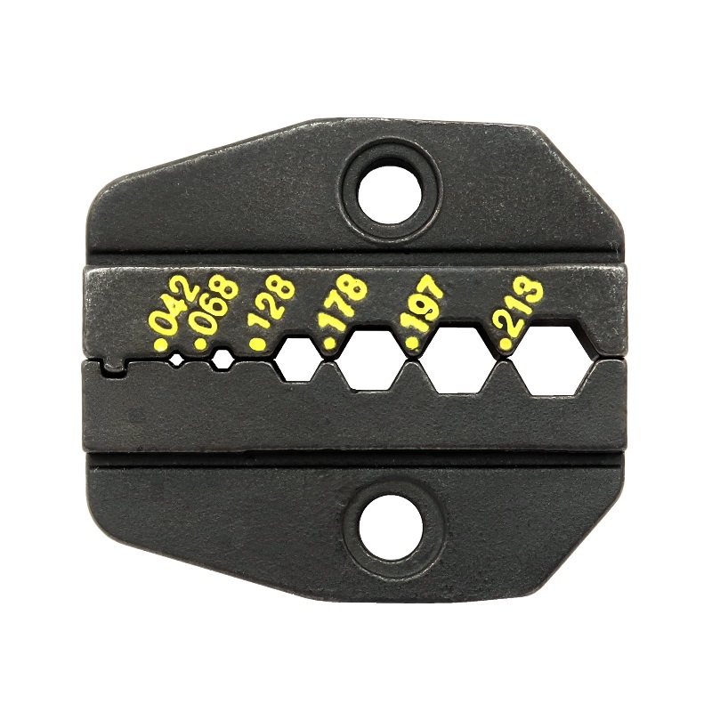
Crimping Guide:
Use the 0.052” hex die from your 7505-DIE-174 ratcheting crimper die to crimp the center pin above the small lip of the center pin right on top of the “solder hole”.
Die Only
P/N: 7505-DIE-174
Die and Tool Kit
P/N: 7505-HANDLE-174
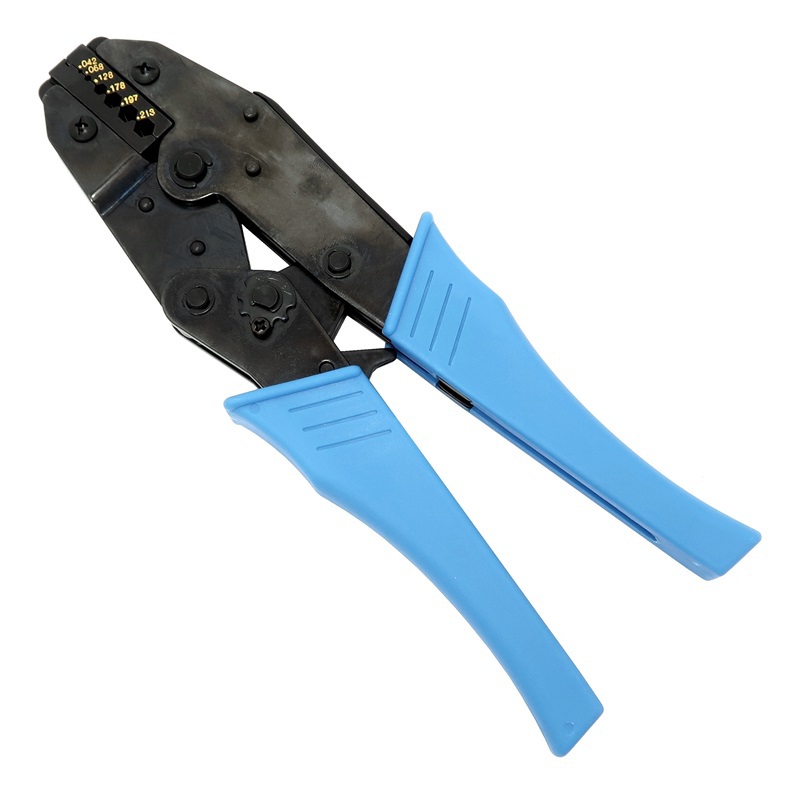
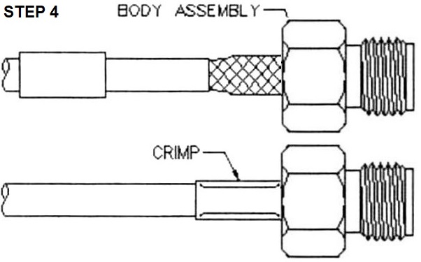
Crimping The Ferrule:
Flare out the braid of the coax and slide the body assembly over the center pin and under the braid. Then seat the body assembly firmly onto the center contact. Arrange braid uniformly around the knurled portion of the body assembly. Slide the ferrule (crimp sleeve) forward and make sure it is in contact with the body assembly. Using the 0.213” hex die from the 7505-DIE-8X ratcheting crimper die to crimp the ferrule (crimp sleeve) right up next to the main body assembly. This crushes the metal sleeve around the braid and knurling to make it difficult for the connector to be removed. Trim any braid that extends out from crimp sleeve, against the body assembly, so not have any strays sticking out.
Final Testing:
When this is completed, as a final test, you should always check resistance from the center pin to the body with an ohmmeter in a low resistance scale. After verifying that there are no braid – to – center pin shorts on the other end of the coaxial cable, you should see infinite resistance (open). This completes your SMA female crimp-on connector installation, and the connector is ready for use!
See our entire line RF Connectors and Adapters:
RF Connectors
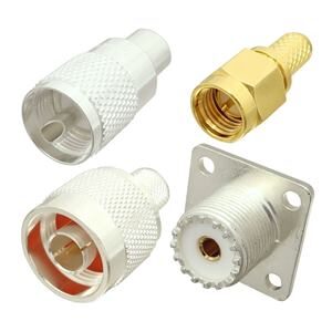
RF Adapters
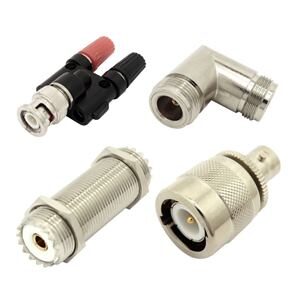
About Max-Gain Systems, Inc.
Max-Gain Systems, Inc. carries a full line of in-series, between series, right angle, T-shaped, quick connect, handie-talkie (BLACK), pigtails (coaxial jumpers), etc… RF adapters. Our RF adapter lines are constantly expanding. We keep our RF connector and adapter lines in stock. We ship both retail and wholesale quantities. To become a dealer / wholesale user, contact us with your potential usage.
Max-Gain Systems, Inc. is the number one supplier of fiberglass round hollow tube, square tube and round solid rod to the antenna manufacturing industry. We produce millions of feet a year for hundreds of different industries including but not limited to: marine / boating, aeronautical, agriculture, construction, emergency services, etc…. We have the unique ability to sell one piece or even a semi-truck full. Feel free to prototype using our fiberglass tube and rod then contact us for a quote on a production run. At production run quantities we can cut to your desired lengths at no additional charge, and we can also perform several different fabrications (example: drilling holes in precise locations along a tube) to ensure your delivered material is ready for assembly. We have several accessory items designed for our fiberglass including but not limited to: couplers, telescoping clamps, ferrules, etc…